JK1SXR
=>Japanese
Return to "A. Home"
1. From yagi
to quad antennas
2. Quad antenna
modification 1
3. Quad antenna
modification 2
4. Combined quad
dimensions
Return to "A. Home"
1. From yagi
to quad antennas
2. Quad antenna
modification 1
3. Quad antenna
modification 2
4. Combined quad
dimensions
B2. V/U antennas for low earth orbit satellites
1. From yagi to combined cubical quad antennas1) 144/430MHz combined yagi FOX727 / 1st anntenna for LEO sat
 Aiming at receiving signals of low-earth-orbit satellites (LEO sat), Maldol's HS-FOX727 was used with elevation angle of 30 degree fixed (144MHz 3-element/430 MHz 5-element combined yagi antenna).
This enabled me to receive VO-52 signals very well, and FO-29 too, though somewhat weaker. It was completely new for me to face the so-called Doppler shift, and extreme QSBs. First of all, it is splendid that we can realize both the sat speed and that of radio wave. It had been fully satisfactory for me just to listen to the signals.
One evening, I was listening to VO-52 crawling along ascending orbit at a good elevation. All looked perfect for loop tests. I carefully sent out a series of 435 MHz CW dot signals to the sat. Simultaneously I heard 145 MHz returned signals, astonishingly very clear, in an exactly synchronized fashion to my sending. Wow - - !! that reached to the sat correctly, and returned??!!!
On an another VO-52 path, after listening to the repeated "CQ sat" calls in CW by a JG7*** station, I timed to the call ending, and sent out JK1SXR code, though only a half in belief. Instantly, the station retuned a curt 599 report. Likewise I sent out the most simple one "R 5NN TU" as if there was nothing special. Well, that is a story of 3 years ago, the beginning of my LEO sat communication.
2) Square-quad antenna
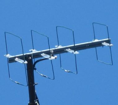
Encouragd by the sucess with such a simple antenna as the FOX727, 2 weeks later I hastily completed previouly conceived square-quad anntennas, 4-element 145 MHz quad and 6-element 435 MHz quad, and replaced the FOX727 sticking out from roof end with the newly built 2 quads (dimensions as in P39-45 on HAM Journal No. 113, "All about cubical-quad").
Different from the FOX727, the sat signal reception became possible even to the sat close to the horizon. On the other hand, there were occasions when I failed to track signals, probably because of the narrowed beam width. To overcome this, modified versoins by reducing element numbers were repeatedly made. 3-element type for the 145 MHz, and 4- and 3-element types for the 435 MHz. Each of these combinations was used for evaluation in actual contacts, for more than a half year. The photo is from one of such trials.
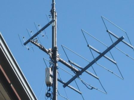
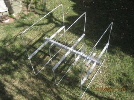
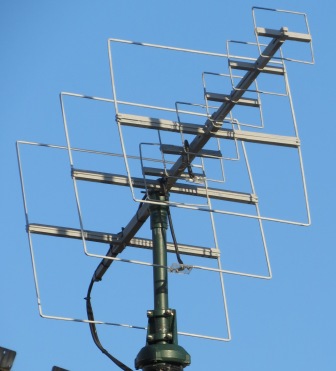
3) 145MHz/435MHz combined square-quad
The appearance of the 2 quads, a small 435 MHz antenna is placed at the opposite side of the 145 MHz quad, was awkward to me. The lateral width was problematic too. This resulted in an another version by inserting the 435 MHz quad into the 145 MHz frame. Though I anticipated a certain decrease in its performance, there was no apprecialbe difference between them. It became very compact and satisfied my liking.
Unknown factors like sat attitude, its battery conditions, or inteferences from the grounds seem to significantly influence LEO sat communications. Thus, in case the antenna evaluation has to be made by actual operations, it will take a certain period of time to make a meaningful evaluation of sat antennas. Again with this combined version, I had tried different combinations of reduced elements for months as in the previous cases.
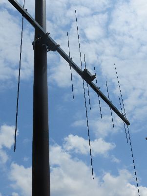
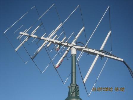
4) Yagi antenna、145Mhz 5-element / 435 MHz 6-element
 Yagi with more elements than FOX727 was tried. 5-element 145MHz and 6-element 435MHz on a boom by referrig to "Inexpensive antenna for VHF/UHF" at JAMSAT site (the original by WA5VJB), lured by the phrase, "amazing performace".
With this combined yagi, soon I noticed that the incidence of severe QSBs increased dramatically. Numeras times I was disturbed by the signals, gyu---iii---, like a sound just before finalizing the song of Tukutukuboshi (a tree cicada singing in late summer around Tokyo area), bobbing up and down, skewing, twisting, - - -. I had never experienced this type of extreme QSBs in my 2-year operation by the quads. Though not remembering very well, the situaiton might have been the same at my early trial stages with FOX727.
Probably I should have tried the so-called cross-Yagi said to be strong to circular polarizations, by adding another set perpedicular to the existing one. However the existing Yagi design already exceeds the quad size by more than twice both in length and width. I was not interested in further complication. Thus this Yagi was abandoned and replaced with the existing quad. This trial ended in convincing me that the quad is better suited for LOE sat applications than Yagi.
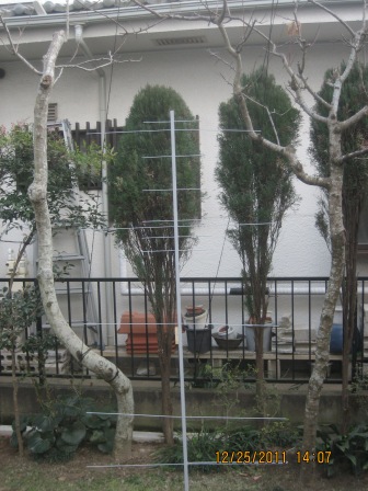
5) [145MHz 3-element / 435 MHz 3-element] quad stack
 Quad stack was also tried. The idea is that in the azimuth rotator only operation, it is preferable to have a broader pattern in a vertical plane as the antenna vertical angle is fixed. Yet we want gains of course. But these factors contradict each other. Thus the parallel stack of 2 identical antenna with low gain and resulting broader pattern could be a solution. So 2 sets of [3-element 145MHz/3-element 435 MHz] quad were newly manufactured. However, the operation result was dissapointing, because the stack width was too short. More spacing between the 2 quads is a solution. However adjacent HF antennas did not allow it.
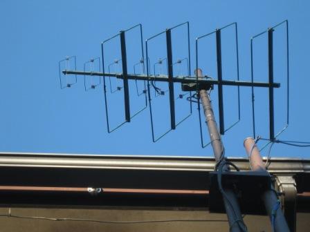
6) 145MHz 3-element / 435 MHz 6-element
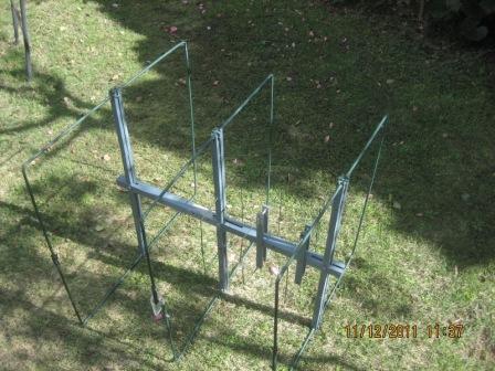
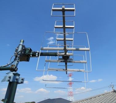 The trial and error in the last few years resulted in a single combined quad, 145 MHz/3-element & 435MHz/6-element. Especially for FO-29 operations, the antenna pattern and gain look well balanced. With its compact appearance, this is supposed to be the summing-up of my long trials.
The quad had been fixed at an angle of 30 degrees. Because of unusual windy days this spring, the quad had become almost horizontal when I noticed it. That's why it had become easier to contact Russian stations via the sat close to the horizon in the north.
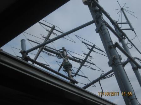
As the head-down quad unexpectedly indicated its effectivness to DX works, an elevation rotator was added so that I can make full use of the antenna performances. Left photo is for the previous style, azimuth rotator only. Right photo for the current one with elevation rotator.
Copyright © 2013 JK1SXR/abemasa. All Rights reserved.